


 199 / 1236

ENGINE
167
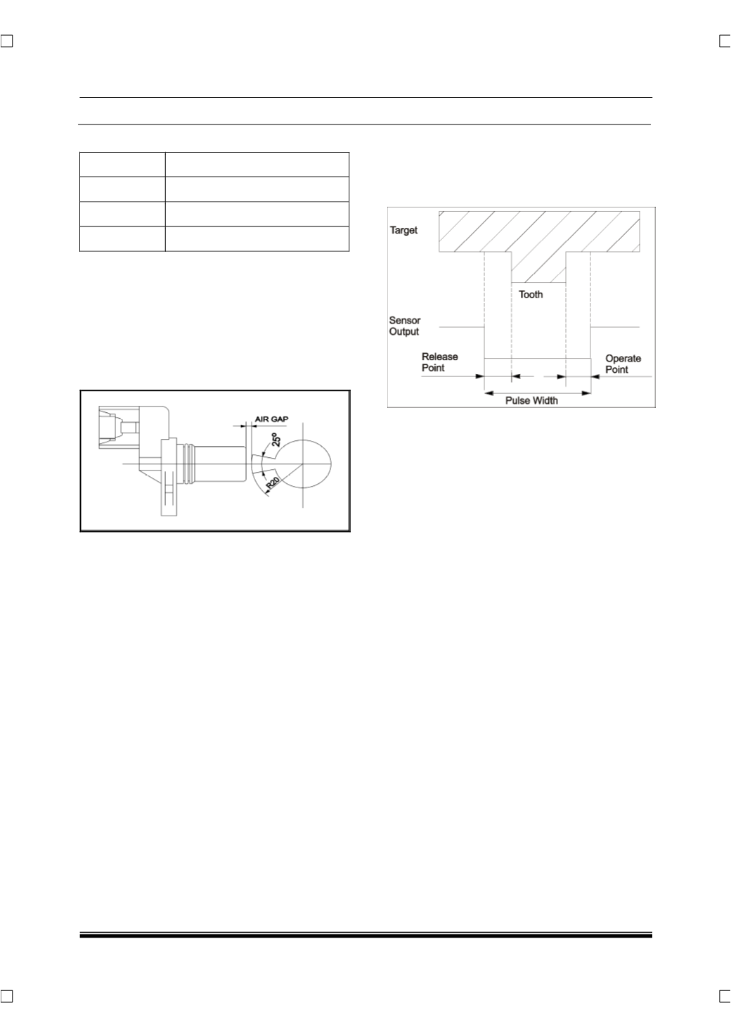
PIN DETAILS
PIN NO DESCRIPTION
Pin 1
Power supply
Pin 2
Signal
Pin 3
Earth
REMOVAL
1. Remove engine cover.
2. Disconnect the wiring harness connector from
cam shaft position sensor.
3. Remove one mounting bolt of sensor and take
out the cam position sensor from its location.
INSPECTION
1. Using multimeter measure the voltage across
the pins of cam sensor.
2. With ignition ‘ON” voltage between pin 2 & 3 is
as below,
•
4.7 V (
When the flag is not in front of the sensor
)
•
0.6V (
When the Flag is in front of the sensor
)
REFITMENT
1. Locate the cam shaft position sensor and fit one
mounting bolt and tighten with specified torque.
Tightening torque for bolt – 1 Kgfm
2. Connect the wiring harness connector to the
cam shaft position sensor.
3. Fit engine cover.