


 109 / 1018

3 CYL PETROL ENGINE
75
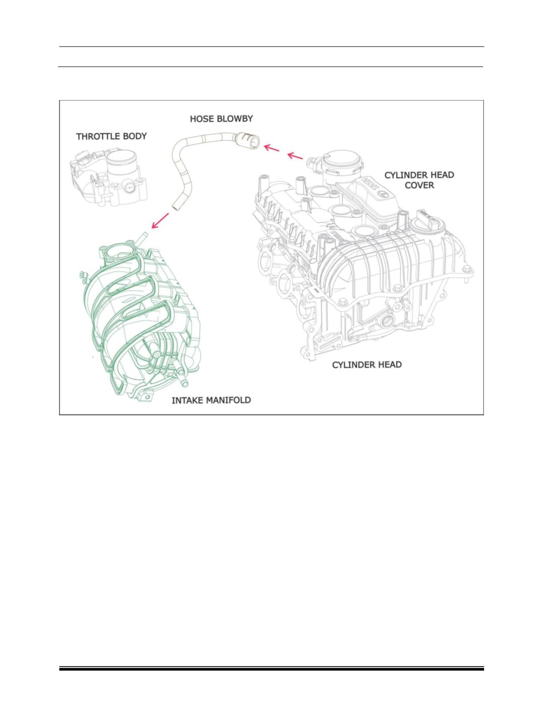
B. BLOW BY SYSTEM :
Blow By Schematic Layout
:
1 Cylinder Head Cover
4 Throttle body
2 Cylinder Head
5 Hose BlowBy
3 Intake Manifold
Description :
In order to reduce the blow by gas emission, the
blow by gas is directed to the intake manifold.
Blow by gases are drawn from cylinder head
cover and crankcase.