


 98 / 1525

59
4 DLT ENGINE
I
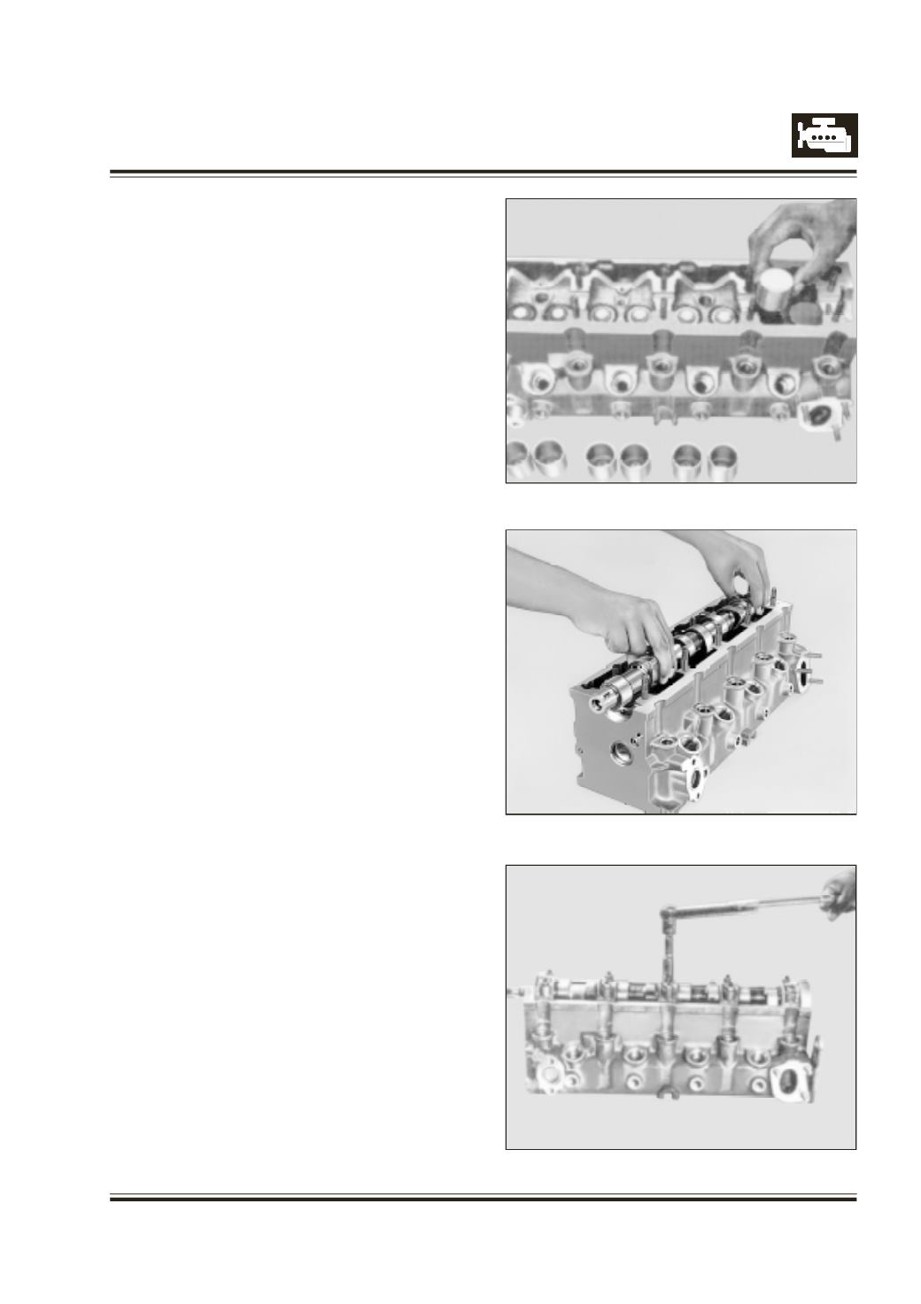
nstall tappets in their respective positions. Refer
Figure 105
S
mear Cam shaft journals and cam lobes with moly
paste grease.
I
nstall cam shaft with arrow mark pointing towards
engine front. Refer Figure 106
I
nstall cam shaft bearing caps in their respective po-
sitions with arrowmark pointing towards engine front.
A
pply ANABOND 611 sealant on parting faces be-
tween 1st & 5th cap and cylinder head.
T
ighten cam shaft bearing cap nuts with NEW
WASH-
ERS
to specified torque (first 3rd cap, next 4th and
2nd caps, lastly 5th and 1st caps). Refer Figure 107
Fig. 105
Fig. 106
Fig. 107