


 923 / 1525

68
ENGINE2.2LDICOR
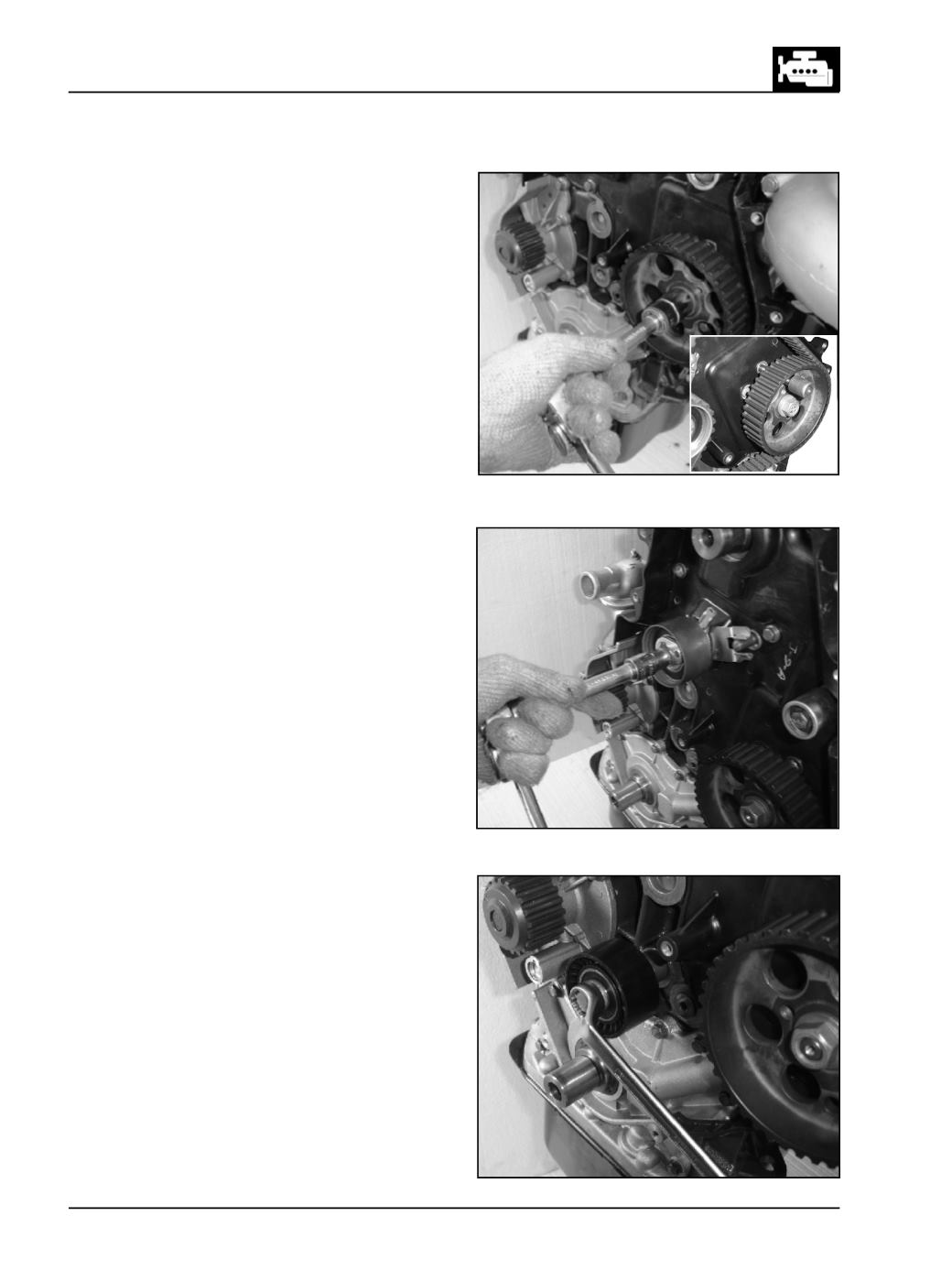
Fig. 161
Fig. 162
Fig. 163
l
Lock the HP pump gear with the help of locking
pin (part no. 2653 5890 06 07) & assemble the HP
pump gear. (Fig. 161)
l
Fit theAutotensioner. (Fig. 162)
l
Fit the Idler pulley. (Fig. 163)