


 519 / 1525

44
BRAKES
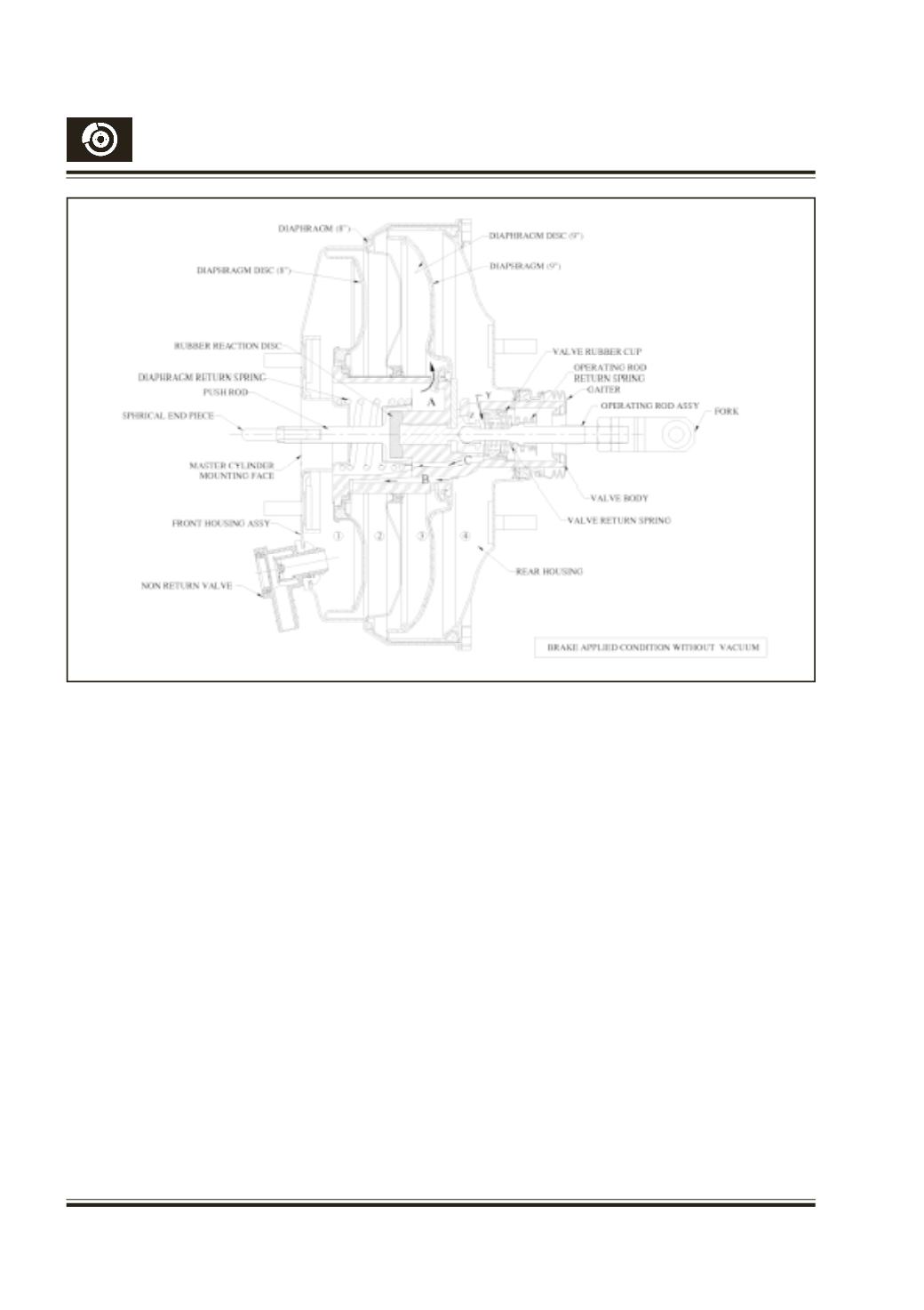
5.5 Brakes on without vacuum (Fig. 48) :
In this condition, all chambers are in
atmospheric pressure. When the pedal is
depressed, the piston moves forward hitting
the rubber reaction disc. In this condition the
vacuum brake valve has no boosting action
and the output force on the push rod is given
as below
Output force = Input force on the operating rod
– Mechanical loss inside booster
The mechanical loss inside booster is mainly
due to spring loads and friction due to seals in
cover and rear housing.
6.
BALANCINGARRANGEMENT :
The balancing action of vacuum brake valve is
by means of rubber reaction disc arrangement
Fig. 43. The input force on the operating rod
moves the operating rod assembly, which
further exerts force on the rubber reaction disc.
The rubber reaction disc acts as a compressed
Fig. 48
fluid transmitting the force from the operating rod
via. the piston to the push rod. The reaction force
from the master cylinder compresses the rubber
disc, which further transmits this force to the
valve body.The valve body balances this reaction
force by moving backwards, closing the air valve.
The boost ratio is given by the ratio of the reacting
areas on the push rod and the piston i.e
Boost ratio
= Area of inner diameter of reaction area of
push rod / Area of Piston
= D
2
/d
2
Where D = Inner diameter of reaction area in
push rod
d = outer diameter of piston
By changing the diameter of piston and the
corresponding diameter of valve body, various
configurations of boost ratios can be obtained.