


 473 / 1525

14
PROPELLER SHAFT
Fig. 15
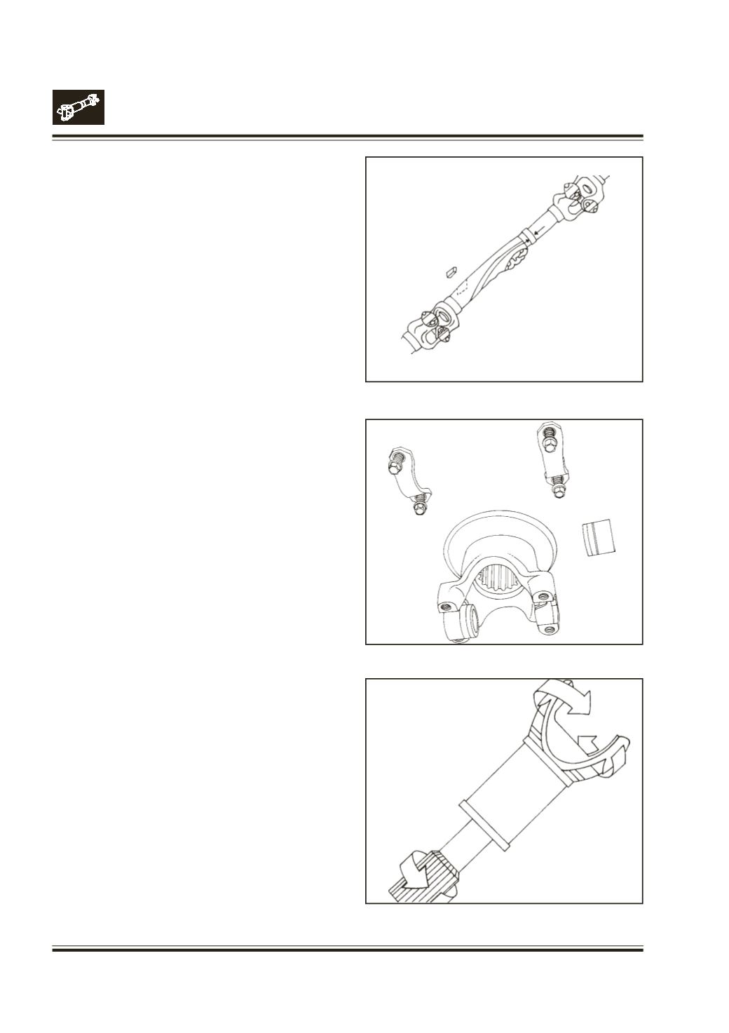
Fig. 16
Fig. 17
Check the shaft for damage, bent tubing or missing
balance weights. Make certain there is no build up of
foreign material on the shaft such as undercoat or
concrete. If found, remove it carefully to avoid damage
to the drive shaft. If shaft is found bent, straighten it.
Fig.15
Check for runout. Check tube for ovality.
Remove the end yoke from the drive shaft and place
in a soft jawed vise to inspect the cross hole surfaces.
Raised metal can be removed with a rat tail or half
round file. Emery cloth should be used to remove all
rust and corrosion from cross hole bores.
Fig. 16
Runout readings are takenwith the drive shaft mounted
in the vehicle with the transmission in neutral and the
axle shafts pulled or by jacking rear wheels off the
ground and placing axles on jack stands.This will allow
rotating the drive shaft by hand to check indicator
readings. The runout readings taken at the various
locations should not exceed an additional 0.25 mm.
Total Indicator Reading over the specified runout.
Fig. 17
INSPECTION OF CENTRE BEARING
Clean all parts thoroughly.
Note :
Do not apply solvent in bearing assembly and
rubber housing.
Check the following :
Condition of splines and threads on shaft.
Condition of splines and holes on coupling flange.
Condition of rubber housing. Replace with new one if
necessary.
Condition of centre bearing bracket bearing surface
and mounting holes.
Figure is only for illustration