


 378 / 1525

15
FRONT AXLE - 4
X
2
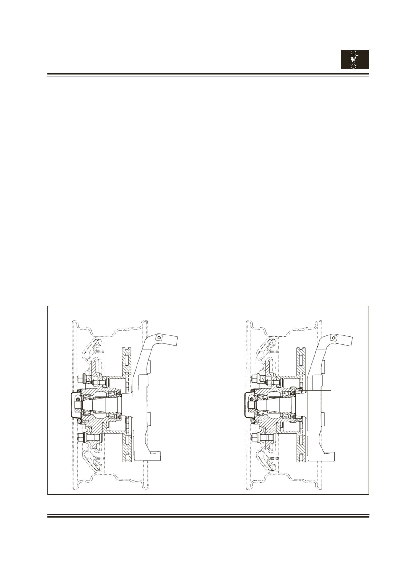
II) INSTALLATION OF HUB ASSY. ON THE
STUB AXLE
(Fig. 9).
a. Slide the assembled hub on the stub axle.
Assemble the spacer & shims of RH side
already stored separately on RH stub axle &
LH side on LH stub axle.
b. Insert the inner race with roller cage of outer
bearing into the stub axle after packing the
rollers with grease, using drift 2651 5890 33
08. Insert the thrust washer and screw on the
split nut.
c.
Wheel Bearing Adjustment:
- Fit the dial gauge on a magnetic stand. Fit the
magnetic stand on the hub and adjust the
spindle of the dial gauge in such a way that it
rests against the face of the stub axle. The
dial gauge should have a pre-load of approx.
2 mm.
- Tighten the split nut with suitable spanner fully.
Loosen the nut slightly, gently tap the hub all
around with a mallet.
ASSY. FRONT AXLE (TATA MOTORS)
Fig. 9
ASSY. FRONT AXLE WITH ABS (TATA MOTORS)
- Check the axial play of the hub on the dial gauge
by pulling and pushing by hand and go on
tightening the split nut until the play is within
the limits of 0.02 - 0.07 mm.
- Tighten the cap screw on the split nut.
- Check and ensure again the axial play of the
hub, that it is within limit of 0.02 - 0.07 mm.
- Fit the hub cover with gasket and tighten the
flanged screws. Fill approx. 30 gms grease in
cover before fitting.
If, new brake disc is to be assembled, match
the marking on hub & brake disc.
d. Install the caliper assy on the disc and tighten
the screws connecting the caliper assy to stub
axle to 6.8 - 9 mkg torque.
e. Connect one end of the brake hose to the caliper
assy by the banjo bolts.
f. Connect other end of the brake hose to the
bundy pipe on bracket on chassis frame. Install
the clip.
g. Fill the brake fluid in the brake fluid container
and bleed the system.
ABS Toner
Ring