


 1130 / 1525

16
FUELSYSTEM2.2LDICOR
Fig. 18
Fig. 19
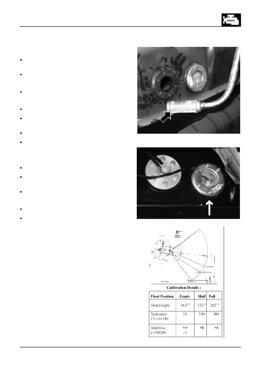
Fig. 20
FUELTANKSTRAINER
It is located inside the fuel tank. (Fig. 18)
Removal
Unscrew banjo bolt and disconnect suction line
from fuel tank strainer.
Unscrew hex screws and pull out strainer.
Inspection
Check strainer mesh for clogging.
Assembly
Clean strainer and refit with a new ‘O; ring.
Connect suction line to fuel tank strainer and tighten
banjo bolt to specified torque.
Always use new sealing washers.
Prime fuel system as mentioned above.
Fuel Gauge tank Unit
Removal:
Remove electrical connections.
Remove 6 screws securing Float unit from the fuel
tank.
Remove the seal from the unit.
Fitment:
Please follow the reverse procedure of Assembly
When installing fuel tank gauge, ensure that fuel
tank gauge unit assembled with ‘O’ ring in place.
Testing /Checking
: (Fig. 20 & 21)
The sender is a float operated rotary potentiometer.
Which provides a variable resistance to ground for the
output from the gauge. When the sender float is at its
lowest point, indicating an empty fuel tank, the
resistance to earth is at its lowest. The resistance
sensed by the gauge, which positions the needle
accordingly.
Use ohm-meter to confirm that the resistance of the
fuel level sensor (Fuel Tank Unit) change with the level
of float position.