


 986 / 1588

99
ENGINE2.2LDICOR
Vaccum management system consists of following
components :
Vaccum pump
Vaccumaccumulator
Electronics vaccum regulating valve (EVRV)
Vaccum tank
Non-return valve (NRV)
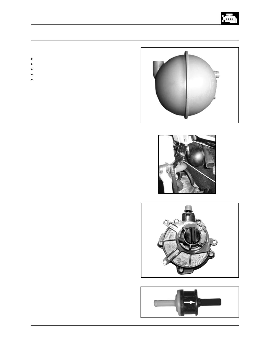
Vaccumaccumulator
(Fig.208)
The vaccum is generated by the camshaft driven
vaccum pump. The vaccum cicuit for the brake and
Engine is separated by the in-line Non return valve
(NRV)
In between NRV and Vaccumaccumulator, there is a T
connector which further connectsEVRVVNTandEVRV
EGR.
The NRV are vaccum accumulator helps in vehicle
performance viz acceleration through gears after
repeated brake stops.
With this system there is no vaccum starvation by VNT
andEGR irrespetive of braking application. TheVaccum
accumulator is mounted on fire wall with the help of a
bracket. (Fig.209)
Vaccumpump
(Fig.210)
vaccumpump supplies vaccum to Brake booster, VNT
and EGR systems. This unit is driven by the exhaust
camshaft.
For removal and fitment procedure please refer engine
over haul section of thismanual.
VaccumTank
For details please refer brakes section of this manual.
EVRV
For details please refer EGR section of this manual.
NRV
(Fig. 211)
This is provided to safeguard the vaccummanagement
system. while assembling NRV the arrowmark should
point towards vaccum pump.
Fig. 208
Fig. 209
Fig. 210
Fig. 211