


 957 / 1588

70
ENGINE2.2LDICOR
Fig. 167
Fig. 168
Fig. 169
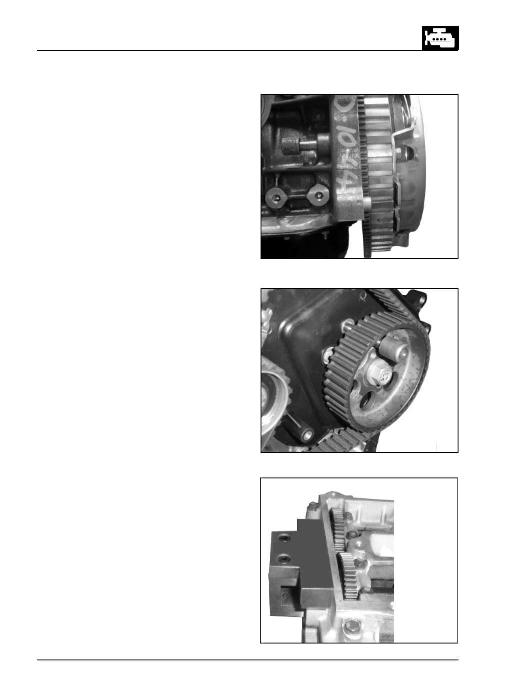
Instruction for Fitment of TimingBelt
Step 1 :
Rotate crankshaft to bring, piston in cylinder
No.1, to TDC position. Lock flywheel in this position
using locking pin (part no. 2653 5890 06 04). (Fig. 167)
Step 2 :
Rotate HP gear to align hole on the HP
mounting bracket & lock the gear with the help of
locking pin (part no. 2653 5890 06 07). (Fig. 168)
Step 3 :
Rotate camshaft, match the timingmarks given
on inlet and exhaust cam shafts and Lock the exhaust
camshaft with the camshaft locking plate (part no.
2653 5890 06 05). (Fig. 169)