


 82 / 1588

53
4 DLT ENGINE
VALVE SEAT INSERTS
F
or removing valve seat inserts from cylinder head
use suitable boringmachine.Bore old insert thin (about
0.5 mm thickness) and then pry it out.
A
lternatively use a suitable turning tool to cut an
annular groove into valve seat insert and then pull it
out with a suitable puller. In order to avoid damaging
machined cylinder head mating surface with crank
case, place any soft protective sheet metal under
supports of puller.
M
easure valve seat insert bore in cylinder head.
I
f boring and prying is done carefully without damaging
valve seat insert bore in cylinder head, fitment of an
over size valve seat insert will not be necessary.
R
e-machined valve seat insert bore in cylinder head
must be exactly at right angle to cylinder head mating
surface with crank case. All specified dimensions
should be strictly maintained to ensure proper
interference of valve seat insert in its bore.
C
lean valve seat insert and seat insert and its bore in
cylinder head thoroughly.
J
ust before installation.
- Place valve seat insert in a mixture of Methenol and
dry ice for about 20-30minutes to bring its temperature
down.
– Heat cylinder head to approximately 80
0
C in water
bath.
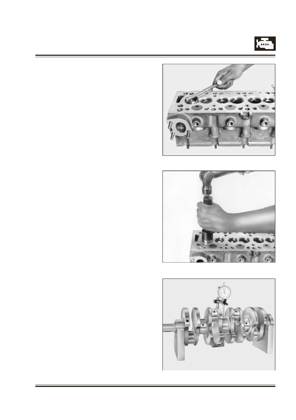
I
nstall valve seat insert in cylinder head bore quickly
by slight hammering. - Refer figures 90 & 91
M
achine valve seat in cylinder head.
CRANKSHAFT
C
lean and carry out visual inspection of crank shaft
for following.
O
ver heating of journals, which is indicated by bluish
brown colour.
S
coring marks on journals.
C
racks, which should be checked on magnetic crack
detector.
C
heck hardness of journals.
C
heck crank shaft run out by supporting it on V-block
at 1st and 5th main bearing journals - Refer Figure 92.
Fig. 90
Fig. 91
Fig. 92