


 678 / 1588

28
ELECTRICALS
Fitment
l
The Switch should be located on the steering
column with Anti Rotation projection engaged on
the column slot.
l
Hold the Switch down against the top of the
column with switch body symmetrical about
column axis and tighten the clamping screw and
check for firm fitment by operating the stalks into
all positions.
l
Fix the nacelle and check for fouling and operation
of the stalks in the extreme positions. Rubber flaps
(if fitted) should not come out of the window in
the nacelle and should not obstruct the movement
of the stalks.
l
Apply contact grease on the horn contact pin and
also smear the same to form a thin film on the
contact face of the contact ring on the steering
wheel.
l
Care should be taken to engage the cancellation
trigger projection into the slots on the steering
wheel boss and check for self cancellation of
RHS / LHS side indicator function and also
clearance between the switch to & bottom of the
spring boss and gap between contact ring and
top of the contact pin guide.
l
Make the electrical connections.
Remove
Please follow reverse procedure (relevant points)
Testing / Checking
No Serviceable Parts Inside, replace if it does not
operate as shown in Fig. 23
Please refer Electrical Circuits of Head Lamp Parking
Lamp System, Front Wiper Washer System.
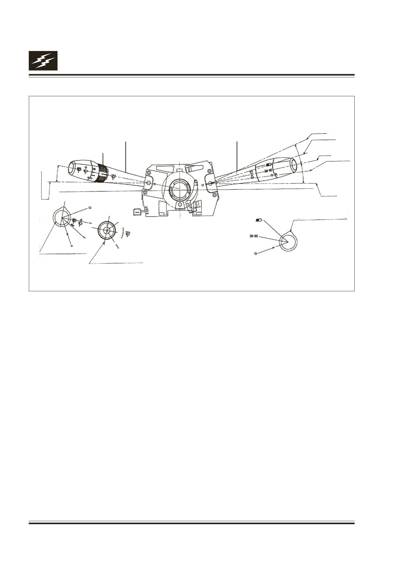
12. COMBI SWITCH :
Fig. 23
SCHEMATIC DIAGRAM OF COMBI SWITCH FUNCTIONS (RHD)
ROTARY POSITIONS OF
LIGHTING SWITCH
LEFT TURN
LEFT LANE CHANGE
NEUTRAL
RIGHT LANE
CHANGE
RIGHT TURN
ROTARY POSITIONS OF WIPER INT. VOLUME
ROTARY POSITIONS
OF WIPER SWITCH
FLICK WIPE
SWITCH
(AUTO RETURN)
(FAST)
(SLOW)
LIGHTING STALK
WIPER STALK
SELECTOR