


 641 / 1588

21
POWER STEERING
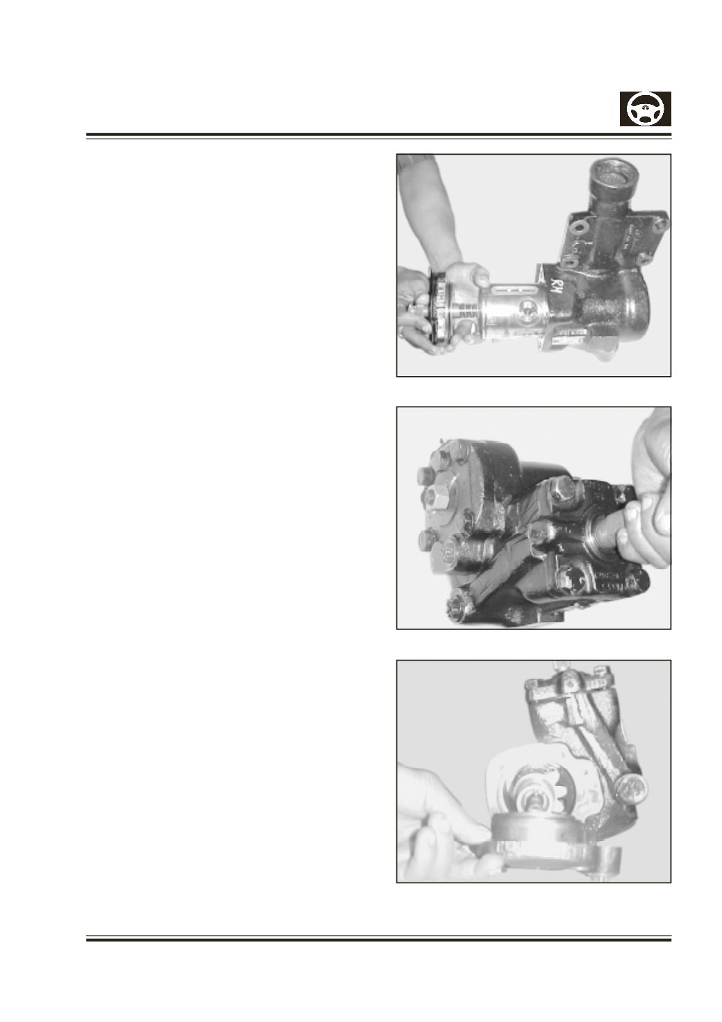
B) Fitting the piston
1. Fit seals (95) in the longitudinal grooves of the
piston and then fit the seals (94).(fig.9)
2. The pair of seals (97 and 98) are also fitted with
the inner seal (97) first and then the outer seal
(98). Place the round seal ring (102) in the recess
of the piston and then fit the piston ring (103).
Special care must be taken when passing the seal
over the piston to ensure that no damage is caused
by the edges of the piston. The small round seal
rings (121) must be adhered to the recess of the
of the cover (128) by means of grease. Lubricate
the cylinder path well with oil.
Slide in the preassembled piston up to the shoulder
with the Tool –2. In order that the seal parts are
not damaged the piston should be fitted in its final
position, i.e. gearing (tooth) parallel to the housing
sector Shaft bore. (Fig. No 9)
C) Fitting The End Cover
1 Screw in and tighten the hexagon bolts (132) with
the washers (131).
Slide the entry bush over the serrated gearing of
the steering spindle, press the shaft seal ring (129)
with the sleeve so deep that the circlip (130) can
just be fitted in its groove (sealing lip pointing
towards the inside of the housing. Fill the space
between the sealing lip and the dust lip with hot
bearing grease) fit the circlip (130) (Fig.No.10)
Refer to the technical data for tightening torques.
D) Pre-assembly of the Cover
.
1. Fit the round seal ring (52) and the seal ring (51) in
the radial groove. Special care must be taken to
ensure that chamfered area of the polyamide ring
lies in the same chamfered surface of the groove.
E) Fitting the Sector Shaft.
1. Bring the piston to the center position by turning
the Input Shaft. This center point is found by first
determining the total number of turns of the worm
then turning back the piston from one stop by
half the total number of turns.
1.2 Insert the segment shaft into the housing, taking
care not to damage the sealing parts.
Fig. 9
Fig. 10
Fig. 11