


 514 / 1588

39
BRAKES
retained inside the diaphragm disc. The
operating rod assembly consists of piston,
valve rubber cup, operating rod, and valve
retaining spring and operating rod return spring.
This operating rod assembly is positioned inside
the valve body by means of key. The rubber
reaction disc is housed inside the push rod,
which is retained in place against the valve
body by the diaphragm return spring which is
resting on the spring retainer. The assembly
consists of four chambers namely 1,2,3 & 4 as
in figure 2. In all conditions of operation, the
chamber 1 and 3 will always be connected
through passage A in the valve body and
chambers 2 and 4 will be connected through
another passage B in the valve body, as shown
in figure 2. There is a vacuum passage C in
the valve body, which connects the chamber 1
with chamber 4. The 8” diaphragm acts as a
seal between chambers 4 and 3, while the 9”
diaphragm acts as a seal between chambers
1 and 2.
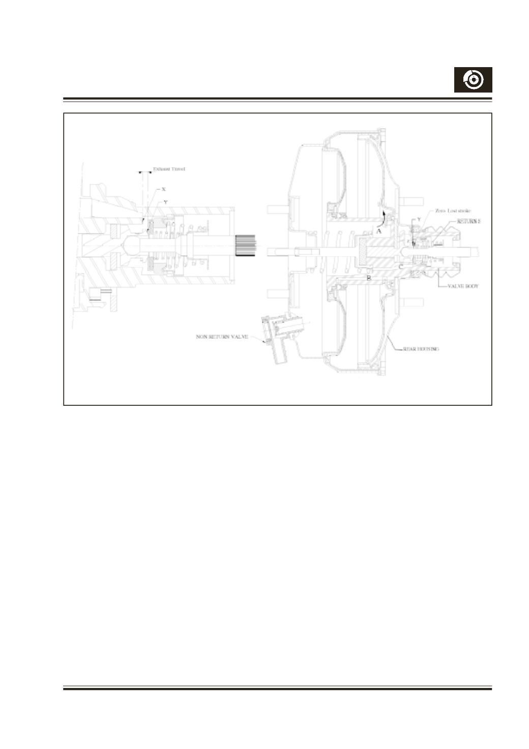
Fig. 43
4.
ZERO LOST STROKE (Fig. 43):
From Fig. 43(a), we can see that the operating
rod sub-assembly is attached to the valve
body, by means of key. Due to the opposing
force of operating rod return spring, the key is
pulled towards the operating rod side, in the
sub-assembly, keeping the vacuum valve (X)
open. But when the valve body sub-assembly
is fitted in the full assembly Fig. 43(b), the
fitted force of diaphragm return spring pushes
the valve body towards the rear housing, till
the key butts against the rear housing. This
movement of the valve body, results in the
closing of the exhaust travel, thereby closing
the vacuum valve and sometimes even opening
the air valve (Y). On application of the vacuum,
the valve body moves forward just enough to
close the air valve (Y) and bring the assembly
to a balanced condition. Hence, at normal
running condition, both the vacuum and air
valve are closed. This feature provides output
force at nearly zero lost stroke of the operating
rod.
Fig. 43a
Fig. 43b