


 344 / 1588

12
SUSPENSION
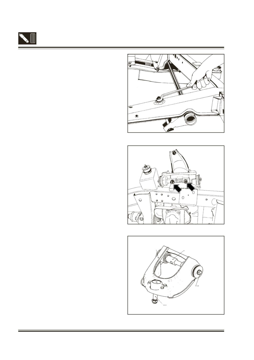
Fig. 9 - Removal of torsion bar
Fig. 10 - Removal of upper wishbone
Fig. 11 - Dismantling of upper wishbone
4D. REMOVAL OFTORSION BAR
(Fig.7)
Caution :
Torsional load is applied on torsion bar by
tightening the lever adjusting nut and lock nut.
Front suspension is working on torsional spring-
ing action of torsion bar.
Before removing torsion bar or upper wishbone
or lower wishbone or ball joints of stub axle
mounting, torsion bar load must be released fully
by loosening lever adjusting lock nut and nut to
avoid flyout of components and thereby causing
any injury.
l
Loosen the torsion bar lever adjusting lock nut
and nut till torsion bar load is fully released.(Fig.9)
Remove lock nut, nut bolt and spherical washer.
l
Pull out torsion bar from mounting bracket on
lower wishbone. Remove lever.
4E. REMOVAL/DISMANTLING OF UPPER
WISHBONE
(Fig.8)
l
Take out the split pin locking the castle nut of the
top ball joint of stub axle.Hold the steering wheel.
Unscrew and remove the castle nut.
l
Push out the ball joint from the stub axle using
special tool Pt. No. 2654 5890 32 01. Properly
support the stub axle.
l
Unscrew and remove the 2 screws (Fig.10)
connecting the spindle on top wishbone to the
bracket on chassis frame, using adaptor
(Pt. No. 2699 5890 4102).
l
Take out the top wish bone complete with ball
joint, spindle etc., collect the shims located
between spindle and bracket.
l
Unscrew and remove the 4 screws holding the
ball joint assembly to the top wishbone. Take out
the ball joint assembly.
l
Unscrew and remove the 4 screws connecting
the top wishbone and spindle. Remove the
washers.
l
Press out the spindle with one pivot bush from
the top wishbone assembly in a press using
suitable brass punch/handle. Press out the other
pivot bush also from top wishbone.
UPPER WISHBONE
SPINDLE
HEX. SCREW
BALL JOINT