


 1376 / 1588

9
CLUTCH
11. INSTALLATION OF CLUTCH ACTUATION
MECHANISM
l
Install clutch pedal bush if removed earlier, using
suitable drift.
l
Locate clutch pedal in the mounting bracket
properly and insert hex bolt.
Note
Smear oil on inside surface of clutch pedal bushwhile
assembling.
l
Fit and tighten two hex nuts with clutch pedal
mounting bolt. Ensure free movement of lever
after tightening.
l
Locate clutch actuation mechanism properly. Push
the eye end and fit it on the mounting pin at
clutch pedal carefully. Install washer and split pin
and bend the split pin.
l
Mount slave cylinder on clutch housing. Make sure
that push rod end is properly located at clutch fork
seat.
l
Ensure that bleeding screw of slave cylinder is at
top. Tighten slave cylinder mounting nuts.
l
Install master cylinder on fire wall and tighten its
mounting screws.
l
Install push rod fork and clutch pedal. Insert clevis
pin. Install plain washer and lock clevis pin with
split pin.
l
Connect pipe connection to slave cylinder.
l
Connect pipe connection to master cylinder
properly.
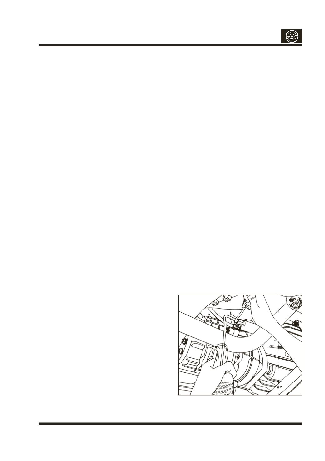
12. BLEEDING THE CLUTCH SYSTEM
The procedure for bleeding the system is as follows :
l
Top up clutch fluid container.
l
Ensure that fluid level in clutch fluid container is
up to ‘Max’ level and not above it. Add clutch fluid
to maintain level while bleeding.
l
Remove dust cap from slave cylinder bleed screw
and clean the screw thoroughly. Attach bleeding
tube to bleed screw and place other end of tube
in a clean glass jar containing sufficient clutch
fluid to submerge tube end.
l
Pump clutch pedal twice or thrice slowly
throughout its stroke and by holding clutch pedal
in depressed condition, loosen bleed screw on
cylinder.
l
Retighten bleed screw on slave cylinder and
repeat the above operation until air bubbles
cease to appear at the end of tube in glass jar,
allowing only fluid to flow.
l
After completing bleeding operation, ensure that
bleed screw on slave cylinder is fully tightened.
Replace dust cap on the bleed screw.
Note
During bleeding process keep a watch on fluid level
in container and top up if the level falls below the
indicated mark.
13. CLUTCH PEDAL LINKAGE ADJUSTMENT
CLUTCH PEDAL FREE PLAY IS DUE TO CLEARANCE
BETWEEN PLUNGER AND PUSH ROD OF MASTER
CYLINDER.THIS CANNOT BE
ADJUSTED.ITIS BUILT IN
DESIGNFEATURE.
l
Ensure before assembling the clutchmaster cylinder
on the firewall that the dimension 128 mm. (Push
rod fork hole centre tomaster cylinder flange face) is
properly adjusted. (Fig.6)
l
Assemble the master cylinder on firewall.
l
Assembletheclutchpedalandthemastercylinderpush
rodforkwithpin, collarbush,washer andsplitpin.
Note
Smear oilwhileassembling thepivot pinof clutch lever.
l
Screw in pedal stopper bolt completely.Press pedal
fully till the pedal bottoms on the floor. Now screw
out the pedal stopper bolt till it touches the pedal
lever, release pedal. (Fig.5)
l
Set the clutchpedal travel to160+5mmby adjusting
clutchpedal stopper.
l
Screw out the bolt further by one turn.Tighten the
locknut.
l
Press the clutchpedal 3-4 times andcheck for proper
functioning.
Fig.9- Bleeding the clutch system