


 505 / 1231

DRIVETRAIN C549
30
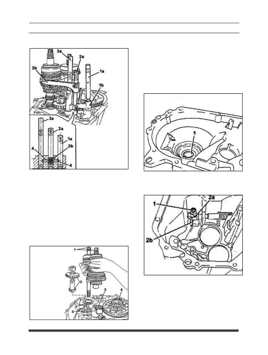
12. Remove the 1st-2nd speed drive rod (1a)
together with the fork (1b).
NOTE: If the rod offers resistance during the
Extraction, the other rods (2a) and (3a) must
be adjusted to move the selectors (4) and (2b).
13. Remove the 3rd-4th speed drive rod (2a).
NOTE: Work carefully to prevent the pawl (2b)
from accidentally coming out.
14. Simultaneously remove 5th-reverse gear drive
rod (3a) and 3rd-4th speed fork (3b).
15. Remove the two gear engagement safety
pawls (4).
16. Remove the main and lay shaft assemblies
(1) at the same time.
17. Remove the reverse idler gear (2).
18. Remove the lay shaft front bearing (3).
19. Remove the differential assembly (4).
20. Remove the magnet (5).
NOTE: The overhaul procedure of differential
assembly is separately mentioned in detail
under
the
head
‘DIFFERENTIAL
ASSEMBLY – OVER- HAUL’.
21. Remove the engine side oil seal for the
manual TRANSAXLE bell housing.
22. Unscrew the gear control selector bolt.
23. Remove the pin (2a) using a suitable drift and
remove the gear selector (2b).