


 446 / 1231

ENGINE 1.3L QUADRAJET (90PS)
109
OPERATION
The accelerator pedal position is converted into an
electrical voltage signal and sent to the injection
control unit by the potentiometer connected to the
pedal.
The accelerator pedal position signal is processed
together with the information relating to the engine
rpm to obtain the injection times and the pressure
PIN OUT
Pin
Description
Signal type
1
Track 2 supply 5 V input
2
Track 1 supply 5 V input
3
Track 1 earth Earth
4
Track 1 signal
Analogue output
5
Track 2 earth Earth
6
Track 2 signal
Analogue output
BOSCH SENSOR TECHNICAL SPECIFICATIONS
Supply voltage: 5 V +/- 0.3 V
Resistance at potentiometer cursor terminals: 1
Kohm +/- 0.4 kOhm
Track 1 resistance: 1.2 Kohm +/- 0.4 kOhm
Track 2 resistance: 1.7 Kohm +/-0.8 kOhm
HELLA SENSOR TECHNICAL SPECIFICATIONS
Supply voltage: 5 V +/- 0.3 V
Resistance at potentiometer cursor terminals: 1
kOhm +/- 0.4 kOhm
Track 1 resistance: 0.9 kOhm +/- 35%....1.4 kOhm
+/- 35%
Track 2 resistance: 1.2 kOhm +/- 35%....2.0 kOhm
+/- 35%.
H. AIR FLOWMETERWITH BUILT INAIR SENSOR
SPECIFICATIONS
The debimeter is located on the air intake sleeve
and is hot film type.
The intake air temperature sensor is built into the air
flow meter on the same support as the sensitive
element.
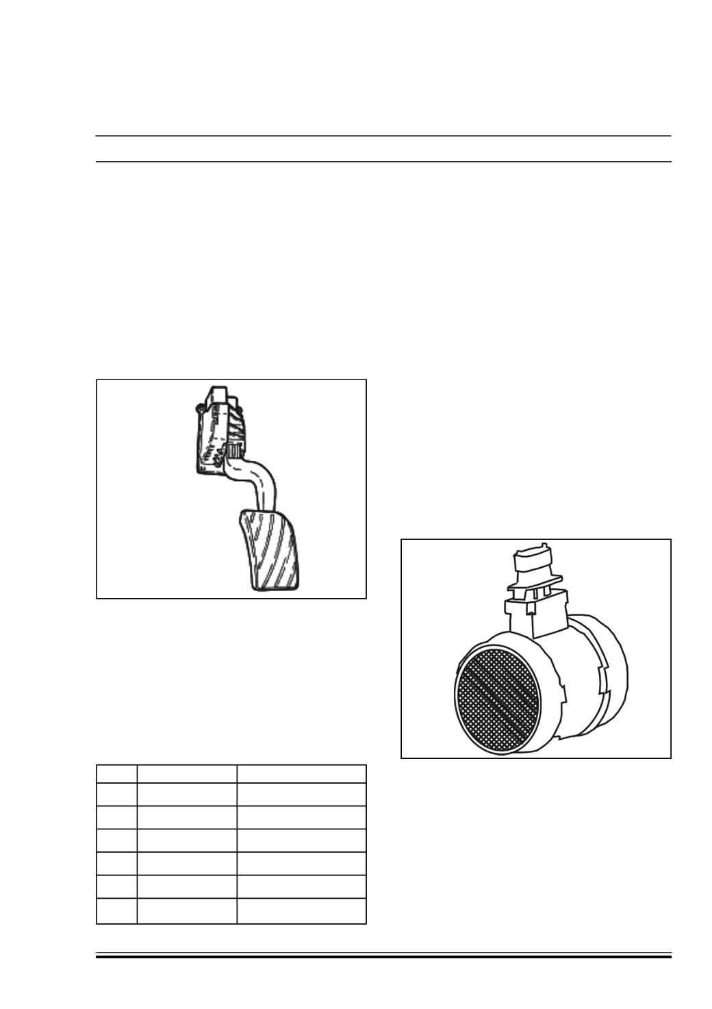
G. ACCELERATOR PEDAL POTENTIOMETER
CONSTRUCTION SPECIFICATIONS
The sensor is secured to the accelerator pedal; inside
it contains an axially-located shaft connected to two
potetiometers : a main one and one safety one.
A coil spring on the shaft ensures the correct amount
of resistance to pressure while a second spring
ensures return following release.
The redundant signal reading makes it possible to
continuously monitor the plausibility of the readings
in order to guarantee complete safety whilst driving
even if there is a failure.