


 573 / 896

STEERING SYSTEM
581
STEERING
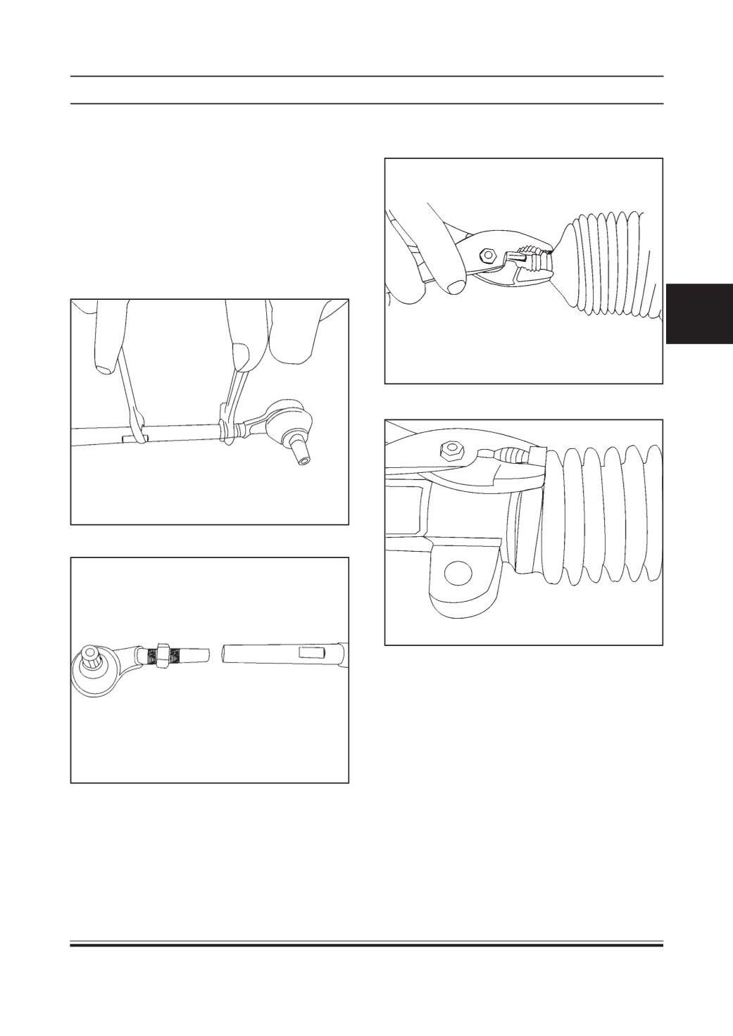
2. Take out outer ball joint assembly. (14 & 15)
3. Remove the bellow clips (19) on either side using
the plier
4. Remove bellow strap (20) on either side
1. Remove lock nut (16) of the outer ball joint
assembly. (14 & 15)
Disassembly
NOTE :
1. RPS assembly already removed from vehicle.
(Refer RPS assembly removal procedure)
2. Refer exploded view of
Steering Rack and Pinion
Assembly (For M/S SONA) while overhauling
procedure.