


 285 / 896

ENGINE 273 MPFI
271
ENGINE
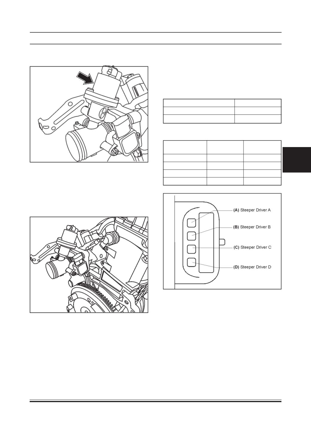
INTAKE AIR CONTROL VALVE (IACV) / ISC
VALVE
Pin Details
Signal
Connector
ECU
Pin No.
Pin No.
Stepper DriverA
A
37
Stepper Driver B
B
38
Stepper Driver C
C
26
Stepper Driver D
D
25
Pin Configuration
Stand Alone Diagnosis
Insulation Resistance between the pins >100MOhm
Inductivity (at 25 °C) 38 Mh +/- 15%
SystemDiagnosis
•
Use TATAdiagnostic Tool.
Location
This actuator is part of integral throttle body which is
fitted on intake manifold upstream side. Preferred ori-
entation of shaft is horizontal in direction of the crank-
shaft.
The maximum tightening torque of fixing screws is 10
Nm.
Working Principle
Intake air control valve is the part of the mechanical
throttle body. This valve allows accurate flow control
by varying flow cross section area. This is done by
moving the spindle in both open/close directions op-
erated by a stepper motor.
Installation Details
Preferred orientation of shaft is horizontal in direction
of the crankshaft.
The maximum tightening torque of fixing screws is 4
to 5 Nm.
Storage Conditions
Storage Temperature
-40 °C to 130 °C
Maximum Storage Time
3 Years
Operating Temperature range -30 °C to 120 °C