


 152 / 654

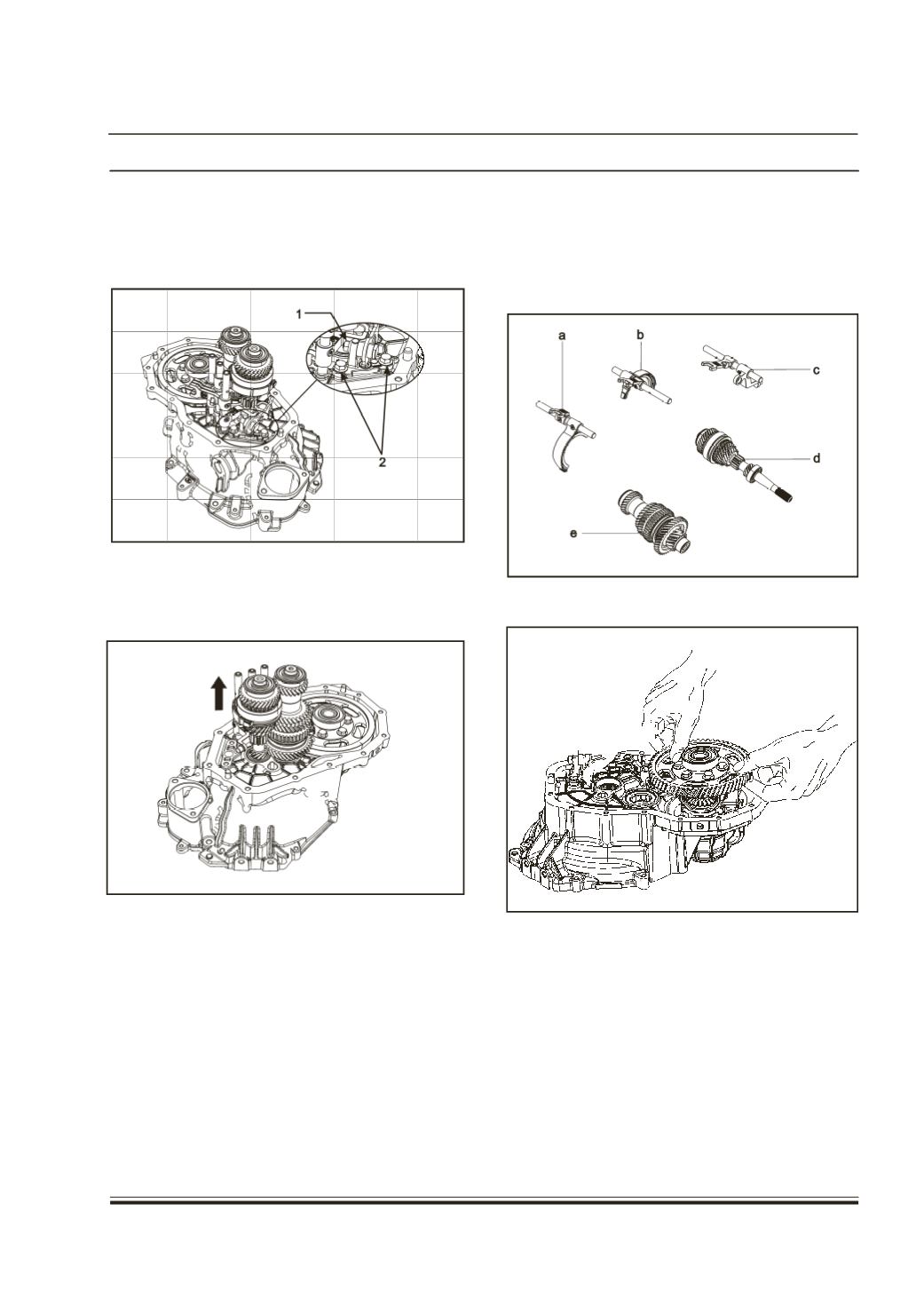
16. Rem
loos
M8
refe
ASS
17. Lift
with
ove the rev
ening the pi
bolts (2). For
r ‘SHIFTER
EMBLY’ OV
the Input an
the three Sh
erse idler br
nion (1) and
further disma
SHAFT AN
ERHAUL
d lay shaft a
ifter Shafts.
acket assem
unscrewing t
ntling of the
D SHIFTER
ssembly alo
bly by
he two
bracket
FORK
ng
18. Separa
a. Firs
b. Sec
c. Rev
d. Inp
e. Lay
19. Remov
Note:
The O
separately i
te out the fol
t – second s
ond – third s
erse shifter s
ut shaft asse
shaft assem
e the differen
verhauling
n their respe
DRI
lowing
hifter shaft
hifter shaft
haft.
mbly.
bly.
tial assembl
of subassem
ctive section
VETRA
assembly.
assembly.
y.
blies are giv
s.
IN
27
en