


 114 / 654

DRIVETRAIN
335
DRIVETRAIN
Fitment:
For fitment follow the reverse order of the removal
procedure, using the Tool 2834 5890 25 01 (Clutch
Mandrel) and tighten the M8 bolts to a torque of 3.2
Kg m.
Do not mix clutch mounting bolts with other
fasteners. Do not use longer or shorter screws.
Longer screws may not tighten the clutch at all.
Shorter screws will not provide enough threads to
achieve desired tightening.
While tightening clutch mounting screws check
aligning mandrel for continuous free sliding to
ensure concentric installation of clutch disc which
will avoid trouble during installation of transaxle.
NOTE
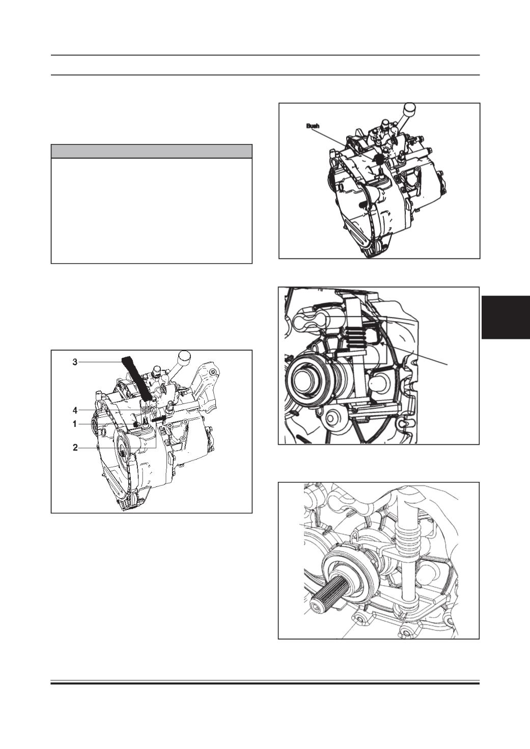
4. Remove upper bush on housing.
(b) Clutch Actuation Mechanism Overhaul
Disassembly:
1. Remove the hexagonal nut (1) & bolt (2) to loosen
clutch release lever (3).
2. Now take out the clutch release lever (3).
3. Remove external return spring (4).
5. Disconnect the internal return spring from the front
half housing.
6. Disconnect the clutch release bearing by releas-
ing the locking clip.