


 945 / 1006

836
HVAC
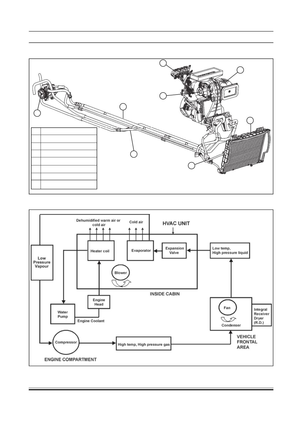
HVAC SYSTEM LAYOUT
1 AC compressor
2 Refrigerant lines/pipes
3 Heater lines/pipes
4 HVAC control panel
5 HVAC unit
6 Blower assembly
7 Condenser assembly
8 Pressure switch
SCHEMATIC OF A/C SYSTEM
1
2
4
6
5
8
7
3