


 581 / 1006

STEERING
2
1.1.3 GENERAL DESCRIPTION
The
EPAS
(electrical power assist steering - column
Type) is made up of the following components
The system consists of the steering column (2) and a
servo unit (4). The steering torque is transmitted via
the intermediate shaft (5) with universal joints (6) to
the mechanical rack and pinion steering (7). Sensor
technology and torsion bar are next to the helical
gear drive in the servo unit (4). The helical gear drive
converts the support torque generated by the servo
motor (4) and transmits it to the intermediate shaft
(5). The support torque and operating torque of the
steering wheel generated are transmitted via the in-
termediate shaft (5) to the rack-and-pinion steering
(7) and then to the wheels. If the vehicle power sup-
ply or electrical supply fails, then the vehicle can still
be steered due to the mechanical connection be-
tween the steering wheel and the wheels being
steered.
In Nano EPAS speed base assistance feature is con-
figured which provides the different motor assistance
at different speeds which is called as boost curves.
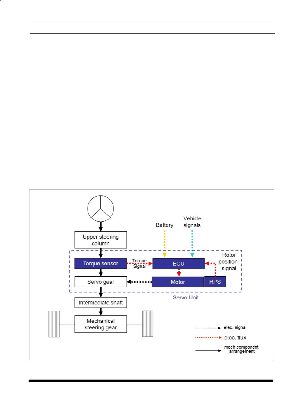
FUNCTION
The torque sensor in servo unit registers the steering
torque and steering speed once the driver performs
a steering motion.
All data (including the vehicle signals such as engine
speed, vehicle speed, ignition signal) is transmitted
to the control unit (ECU). This then calculates the
necessary support torque and on the basis of the
calculated results, controls the servo motor (4).
A rotor position sensor is attached to the servomotor
(4). An index sensor is integrated in the torque sen-
sor.
The control unit (3) uses the integrated index sensor
and the rotor position sensor to calculate the steering
wheel’s steering angle.
Depending on the programming, the steeringwheel’s
angle signal can be sent back to the vehicle.
BLOCK DIAGRAM OF EPAS SYSTEM
: