


 1398-1399 / 1904

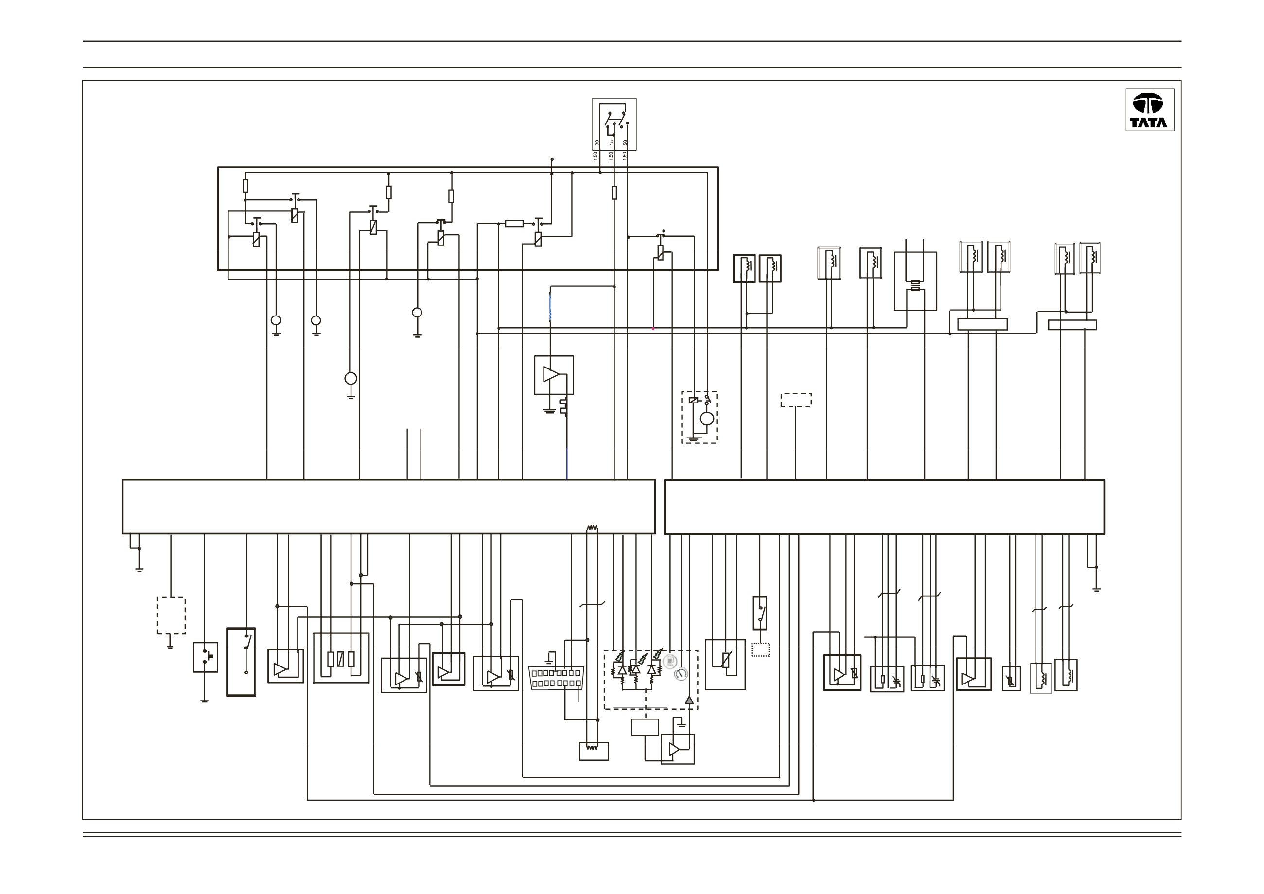
ELECTRICAL
CIRCUIT SCHEMATIC OF EMS ECU (SHEET 3 OF 5 )
UPDATED -FOR SERIES VEHICLE ASSEMBLY
As per BOSCH ECU Block ver 2.4
Canister
Purge
Valve
CNG Gas
Pressure
Regulator
CNG Gas
Injector
Cylinder2
CNG Gas
Injector
Cylinder1
Injector
Cylinder1
Injector
Cylinder2
To
Cyl.1
To
Cyl.2
Ignition Coil
gnition supply
Starter
Relay
(NC Type)
Main
Relay
+ V batt
AC Fan Relay
Radiator
A/C compressor
Relay
Valve1
CNG Gas Tank
Valve2
Fuel Pump
Relay
1 2
1
+
2
-
+ -
2
1
1
2
1
+
4
-
1
+
4
-
+ -
1 2
+ -
1 2
2
Primary
Secondary
1
I
Fan
Relay
AC Fan motor
M
Radiator Fan motor
M
1
+
2
1
+
2
-
-
Fuel pump motor
M
Sensor
Supply
ter Purge Valve
Pressure Regulator
Alternator
r DF- Input
G Gas Injector 2
G Gas Injector 1
uel Injector 2
uel Injector 1
tion coil
n Switch KL-15 supply
rank KL-50
lay driver
Supply After Main Relay
Supply After Main Relay
M
S
hibit Relay
AC fan relay
Radiator fan relay
C
AC compressor
mpressor
Command
_H
N_L
CAN
Application
Command
Command
mp relay command
+
s
Gnd
ueling
signal
3
1 2
Gasoline EMS ECU - VehicleConnector 1
Gasoline EMS ECU -Engine Connector 2
Canis
235
CNG
240
gnal
re 226
225
208
al
215
205
233
Alternato
S+
S-
201
213
gnal
109
104
CN
CN
F
244
243
224
212
F
al
231
250
247
D
237
238
154
153
ne
139
132
_H
144
N_L
232
nal
129
123
nal
101
t
117
m) 236
m)
242
219
put
2
r 1
l 2
nal 1
246
239
230
202
204
e
112
103
y
125
208
d
or
ly
203
207
223
217
227
nal
110
137
l
124
256
Igni
Ignitio
116
C
245
Main Re
Battery
155
156
115
Battery
tarter
Solenoid
& Motor
Starter In
140
141
131
AC Co
Relay
145
133
CAN
CA
nput
136
A
D
B
C
151
152
149
150
C 113
134
206
252
251
Valve 2
Valve 1
Fuel Pu
142
241
CNG Ref
Interlock
146
120
102
CNG Rail Pressure si
Gnd
CNG Rail Temperatu
Coolant Temp. Sign
Gnd
VR
VR
CNG Tank pressure si
GND
Camshaft Sensor sign
Gnd
Chassis
GND
Knock Sensor GN
Knock Sensor signal
Chassis
Gnd
K-diagnostic li
High Speed CAN
High speed CA
Vehicle Speed Sensor Sig
MIL LED
Note 4
Coolant Level sig
Coolant
Level
Sensor
HTW LED (pwm)
Low Fuel inpu
Gasoline\ CNG mode LED (pw
CNG Fuel Level (pw
Reverse Gear In
1
2
O2 CAT Heater
O2 CAT Heate
O2 Sensor Signa
O2 Sensor Sig
Gnd
Gnd
Battery
Supply
after
Main
Relay
ManifoldAir pressur
ManifoldAir temp 227
Gnd
+5V Sensor Suppl
Gn
Thp pos. sens
+ 3.3V Supp
1 2 3
Oil Temp Input
ManifoldAir temp
+5V supply
AC pressure sig
Oil Pressure Signa
A/C Request I
1
equest
A D B C
Stepper
Stepper
Stepper
Stepper
Stepper
Stepper B
CNG Gas Mode Selector Switch
A
CE LED
+ s
-
CNG Rail
Pressure &
Temp Sensor
(Sensata)
t
1 2
Coolant
Temp.
Sensor
Crank-
Angle
Sensor
1 2
+ -
3 1 2
+ s -
CNG Tank
Pressure
Sensor
Mounted on
Regulator
CAM Shaft
Sensor
(PP)
3 2 1
+ s -
+5V Sensor Supply
Knock
Sensor
1 2
+ -
+Ign
-
1
2
Instrument Cluster
Ignition
Supply
CNG
Fuel
level
+Ign
Oil Pressure &
Temp.Sensor
(optional)
Oxygen
sensor
Pre CAT
(Upstream)
Oxygen sensor
Post CAT
(Downstream)
+
+
1 2 3 4
1 2 3 4
3 4 2
+ s
-
1
t
ManifoldAir
Pressure & Temp
(T-MAP) Sensor
Motorized
Throttlewith
Thp.pos.sensor
+5V supply
1 2 3
+ s -
AC
Pressure
Sensor
3 4 2
+ s
-
1
t
2
HVAC
AC R
IGN
Stepper Idle
Speed Actuator
4 2 3
1
B
IMMO
Vehicle Speed Sensor (8ppr)
+
3
Immo - PP